Inadequate balcony drainage can be a significant compliance and performance issue because even a relatively small balcony can generate substantial runoff during intense rainfall events. A blocked outlet combined with insufficient overflow capacity and poor balcony design, can result in water ponding and water entering a building.
This industry guidance establishes a consistent framework for balcony designs and the design of the stormwater drainage systems associated with balconies and similar horizontal elements. The objective is to prevent building damage and reduce risks to health and safety.
Failures in balcony systems may occur due to the following reasons:
Inadequate sizing and location of balcony grate.
Incorrect sizing of associated drains and type of materials utilised.
Incorrect use of leak control flanges.
Provisions of overflow or lack of overflow.
Inadequate waterproofing measures.
Design and construction of balconies, including thresholds at openings serving apartments, between internal and external areas.
When using the Deemed-to-Satisfy (DtS) provisions of the National Construction Code (NCC), pipe size and associated overflows must be designed for each situation. Minimum pipe sizes must be determined based on the relevant catchment area and rainfall intensity.
In most cases, to meet the Deemed to Satisfy provisions of the NCC (AS/NZS 3500.3) a minimum 90mm pipe is sufficient, however it may need to be larger to suit the design flow rates.
In addition, the performance of the balcony relies largely on balcony design, termination height of flashings, waterproofing, and falls to outlets.
Balcony design and stormwater drainage with a building permit.
The architect, designer or engineer are typically responsible for the preparation of balcony designs. The plumber must obtain a copy of the approved design before commencing work. Any variation to the approved design must be assessed and approved by the Relevant Building Surveyor (RBS), and the building permit amended accordingly, before the work proceeds.
The building permit assessment of balcony designs allows for proper coordination between hydraulic design, architectural layout, structural interfaces, balcony design and waterproofing systems.
Balcony design and stormwater drainage without a building permit.
In circumstances where there is no building permit, the plumber is responsible for the balcony stormwater design and the installation of the drainage system under the Plumbing Regulations 2018. The standard of work is to be carried out in accordance with the AS3500.3 and NCC Volume Three, the Plumbing Code of Australia (PCA).
1. Regulatory Framework
1.1 Building Act 1993
Part 2 of the Building Act 1993 (the Act) sets out the standards and framework that apply to building work and Part 3 establishes the requirement for building permits. Section 24(1)(a) states that the RBS must not issue a building permit unless satisfied that the building work and the building permit will comply with the Act, the regulations, and any applicable binding determination.
Part 12A regulates plumbing work, which must comply with the Plumbing Regulations 2018. The Act also requires stormwater work to comply with the Building Regulations 2018.
1.2 Building Regulations 2018
The Building Regulations adopt the NCC: Building Code of Australia (BCA) Volumes One and Two which provide the requirements for the design of balconies. Compliance with these provisions is assessed by the RBS. The design of the stormwater drainage systems forming part of proposed building work, is specifically prescribed in the regulations, stating that it must be approved by the RBS in accordance with Regulation 133.
1.3 Plumbing Regulations 2018
The Plumbing Regulations 2018 adopt the NCC: PCA Volume Three. Installation of balcony stormwater drainage systems, including drainage outlets, prefabricated gutters (excluding in-situ concrete channels), stormwater pipes, and overflow pipework, is regulated plumbing work.
Below ground stormwater drainage systems are defined as drainage work under Regulation 15(1)(b) of the Plumbing Regulations 2018.
Above-ground stormwater piping which receives stormwater from elements that collect and concentrate stormwater (such as roofs, terraces, verandas, awnings, canopies and balconies) must be classified as roofing (stormwater) work under Regulation 25(1) of the Plumbing Regulations 2018.
As regulated plumbing work, balcony stormwater drainage systems must be installed by an accredited person (apprentice or plumber registered in roofing (stormwater), under the supervision of, a plumber who is licensed in roofing (stormwater) work.
In circumstances where a building permit is not required, a stormwater system design must be undertaken and where required, certified by appropriately registered or licensed plumbers in accordance with their authorisations and limitations under the Plumbing Regulations 2018.
1.4 National Construction Code (NCC) 2025
Balcony stormwater drainage systems must comply with all applicable Performance Requirements of NCC Volumes One, Two and Three. Compliance can be achieved through:
Deemed to Satisfy (DtS) provisions; or
a performance solution in accordance with A2G2 of the NCC, or
a combination of both.
1.5 Relevant Deemed to Satisfy provisions
DtS provisions for the design of balconies and balcony stormwater drainage systems appear in:
In Victoria, the PCA (Volume Three) references Standards Australia Handbook 39 (SA HB 39). The NCC provisions override any difference between the NCC and a referenced standard. In addition, where there are any conflicts between AS/NZS 3500.3 and SA HB 39, AS/NZS 3500.3 prevails.
2. DtS provisions
2.1 Deemed to Satisfy Requirements (AS/NZS 3500.3)
AS/NZS 3500.3 Clause 3.8 applies to the design of balconies and terraces. The objective of clause 3.8 is to ensure that the drainage pipe systems for balcony outlets and overflows can accommodate flow rates appropriate to the catchment area and associated Annual Exceedance Probability (AEP) however, it does not prescribe a methodology to achieve this.
In most cases to meet AS/NZS 3500.3 a minimum 90mm pipe is sufficient, however it may need to be larger to suit the design flow rates.
In such cases, the Following calculation methods may be relevant.
2.2 Calculations
It should be noted that pipe sizing methods used throughout the standard are based on the Colebrook-White / Darcy-Weisbach equations. Although this is not presented in full within the standard, the equation can be used to demonstrate compliance with DtS provisions of the NCC, as explained in Vic A5G4(6)(a) of the PCA and A5G3 of Volumes One and Two of the BCA.
The water-carrying capacity of a pipe depends on several factors:
Pipe diameter
Pipe length
Internal roughness (material type)
Hydraulic head (height difference between the outlet and overflow)
Pipe gradient (slope)
Number and type of bends and fittings.
Standards Australia Hand book 39 includes an informative note stating that balcony drainage can be designed using the general design and sizing principles applied to roof drainage systems in AS/NZS 3500.3. This approach is appropriate because the roof drainage design methodology explicitly accounts for the relationship between outlet size, overflow height, sump and box gutter depth. As a result, the hydraulic head is inherently incorporated into the calculated flow capacity of the outlet and downpipe.
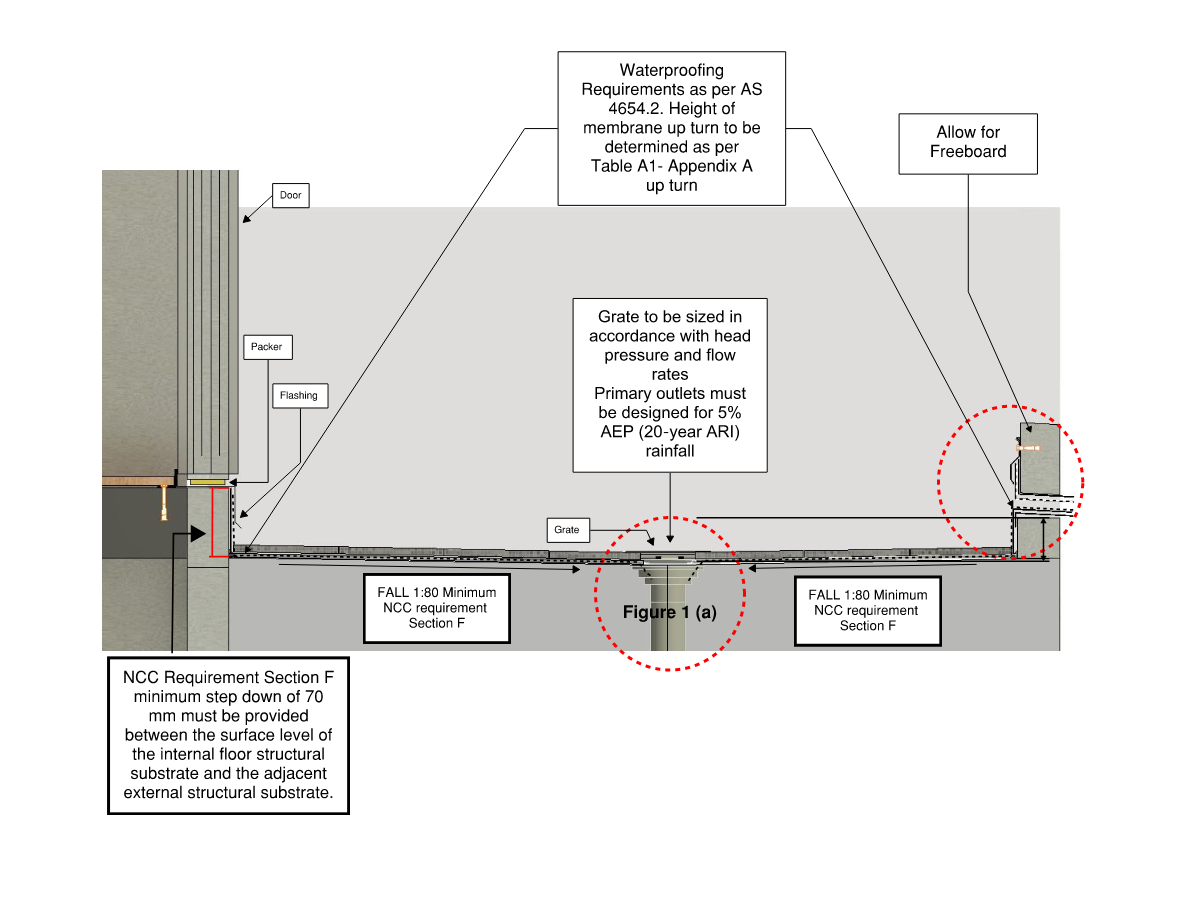
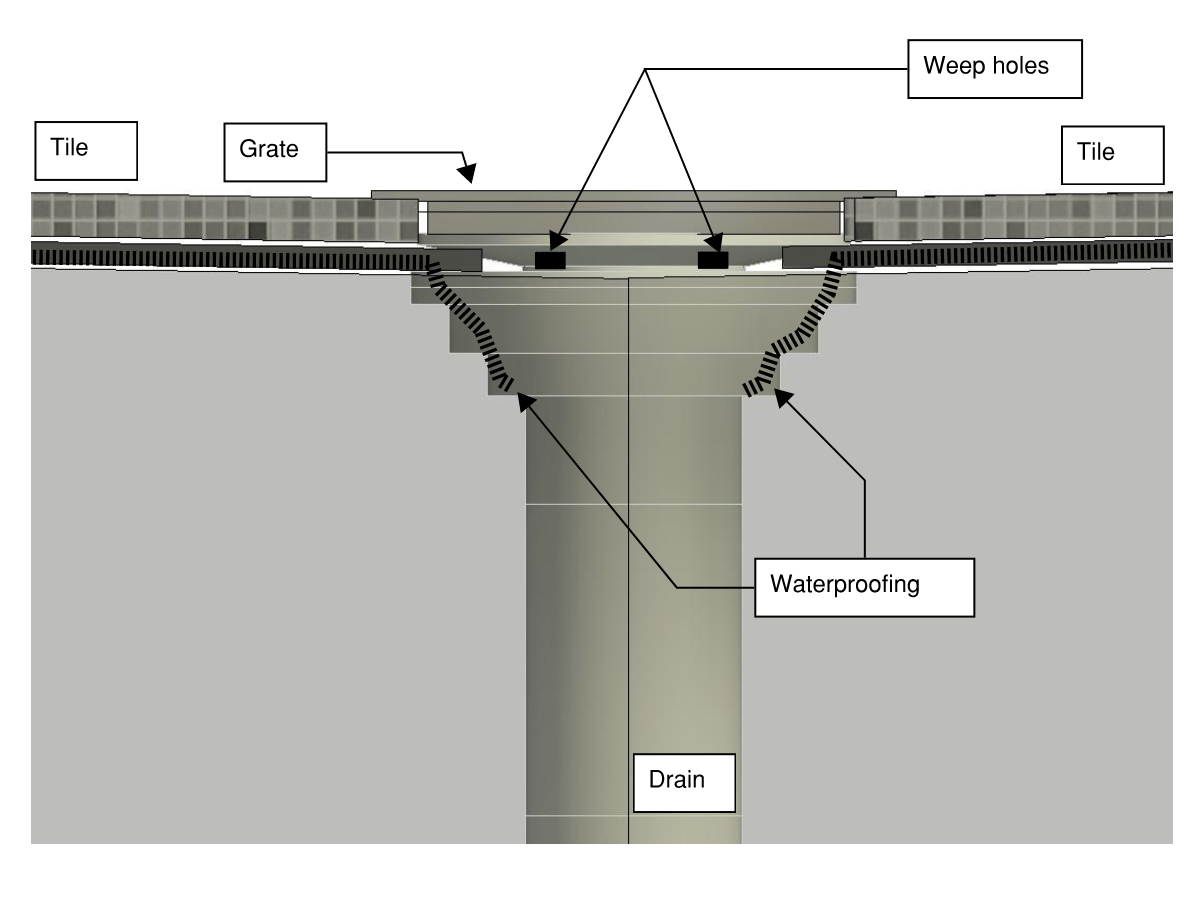
Caution: Grate designs may require a larger effective surface area to accommodate the flow rate which has been calculated for the balcony surface water. It is essential to check the manufacturer’s specified maximum design flow for the grate and confirm that it matches the calculated outlet flow rate. Refer to Figure 1 and 1(a) typical grate detail.
Caution
Grate designs may require a larger effective surface area to accommodate the flow rate which has been calculated for the balcony surface water. It is essential to check the manufacturer’s specified maximum design flow for the grate and confirm that it matches the calculated outlet flow rate. Refer to Figure 1 and 1(a) typical grate detail.
3. Performance Solutions
A performance solution associated with a building permit must consider both the BCA and PCA. A performance solution prepared under the PCA should be presented to the RBS, to consider whether any relevant Performance Requirements under the BCA and PCA have been impacted.
The Performance Requirements, which aim to ensure the safest and controlled collection and disposal of stormwater, and the prevention of water ingress in buildings include:
BCA: Vol 1 F1P1
BCA: Vol 2 H2P1 and H2P2
PCA: E3P1, E3P2, E3P4, E4P1, E4P2
Where a building permit is not required, a performance solution under the PCA must be in accordance with A2G2 of the PCA.
In all cases, performance solutions are required to be attached to the plumber’s compliance certificate.
4. Design of Balconies
It is extremely important to design a balcony correctly. Poor balcony design and inadequate drainage provision are the most common cause of water ingress in buildings.
A properly designed balcony should include:
Adequate falls towards drainage points at a minimum of 1:80
Appropriately sized drains
Overflow provisions so water can escape if the primary drain becomes blocked
Waterproofing membranes installed in accordance with relevant standards
Thresholds and upstands that prevent water entering a building
Consideration of the design rainfall intensity for the catchment area.
The structural substrate and associated waterproofing must incorporate a minimum fall of 1:80 towards the drainage system.
5. Balcony overflow requirements
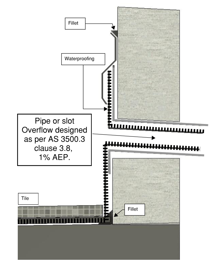
Clause 3.8 of AS/NZS 3500.3 requires an overflow to be designed for rainfall events with an Annual Exceedance Probability (AEP) of 1%. However, hydraulic capacity of the outlet pipe alone is insufficient, and the size, location, height, and configuration of the overflow outlets are critical in ensuring the effective performance of the balcony drainage system.
The overflow weir level must be set above the maximum hydraulic head of the primary outlet to ensure the primary outlet is operating at its full design capacity, before the overflow becomes active.
To ensure effective operation under surcharge conditions, overflow systems must incorporate a sufficient vertical margin (freeboard) between the top of the overflow outlet and the critical waterproofing system termination height. The freeboard should provide contingency for construction tolerances, surface turbulence and wind-driven inflow. Refer to Figure 1 and 1(b) typical overflow detail.
The invert level of the overflow designed to NCC Volume 1 and Volume 2 DtS requirements, must be installed not less than 20 mm below any adjacent internal floor structural substrate. It is noted that the overflow must be above the hydraulic head of the primary outlet.
This sequencing is essential, to maintain system integrity and to prevent internal water ingress during overflow conditions. The system must be designed holistically to ensure effective conveyance of overflow volumes, without compromising the internal building envelope.